Wednesday, 25 October 2017

WEEK 12 (FYP 1)

FINAL FYP BRIEFING

The last briefing was conducted at usual place, TTL 1 and the attandance is compulsory. The briefing was conducted by Dr. Zulhilmi Mustafa.

The briefing is about :
  • Progress Report
  • Proposal Presentation
  • Proposal Report
Progress Report should be decide, whether want to use logbook or blog. My supervisor prefer me to use blog.

In Proposal Presentation, student should follow the format in preparing slide. Make sure all important point are in the slide according to the marking scheme. Student should wear proper attire.

Proposal Report will consists of content, abstract, preliminary result, conclusion and reference.

Student should follow all the thing that have been brief in Fyp briefing to avoid any problem during presentation day and during submitting progress & proposal report.


LITERATURE REVIEW


Journal 3
This week I want to share about Arduino.

Arduino is an open-source platform used for building electronics projects. Arduino consists of both a physical programmable circuit board (often referred to as a microcontroller) and a piece of software, or IDE (Integrated Development Environment) that runs on computer, used to write and upload computer code to the physical board.

The Arduino platform has become quite popular with people just starting out with electronics, and for good reason. Unlike most previous programmable circuit boards, the Arduino does not need a separate piece of hardware (called a programmer) in order to load new code onto the board - can simply use a USB cable. Additionally, the Arduino IDE uses a simplified version of C++, making it easier to learn the program. Finally, Arduino provides a standard form factor that breaks out the functions of the microcontroller into a more accessible package.

Credit to : Motaz Daadoo and Yousef-Awwad Daraghmi (July 2017) "Smart Water Leakage Detection using Wireless Sensor Networks (SWLD)."


VIDEO


Friday, 20 October 2017

WEEK 11 (FYP 1)

LITERATURE REVIEW

Journal 2
AT89S52 Description

8051 is the name of a big family of microcontrollers. The 89S52 has 4 different ports, each one having 8 input/output lines providing a total of 32 I/O lines. Those ports can be used to output DATA and orders to other devices, or to read the state of a sensor, or a switch. Most of the ports of the 89S52 have 'dual function' meaning that they can be used for two different functions.

The first one is to perform input/output operations and the second one is used to implement special features of the microcontroller like counting external pulses, interrupting the execution of the program according to external events, performing serial data transfer or connecting the chip to a computer to update the software. Each port has 8 pins- variable called 'register', each bit being connected to a different input/output pin.

There are two different memory types: RAM and EEPROM. Shortly, RAM is used to store variable during program execution, while EEPROM memory is used to store the program itselft, that's why it is often referred to as the 'program memory'. It is clear that the CPU (Central Processing Unit) is the heart of the micro controllers. It is the CPU that will Read the program from the FLASH memory and Execute it by interacting with the different peripherals.

Credit to : Ria Sood, Manjit Kaur and Hemant Lenka (June 2013) "Design and Development of Automatic Water Flow Meter."


VIDEO


Friday, 13 October 2017

WEEK 10 (FYP 1)

4TH FINAL YEAR PROJECT BRIEFING

The fourth briefing was conducted at usual place, TTL1 and the attendance is compulsory. The briefing was conducted by Dr. Mohammed Reyasudin Basir Khan.

Date : 13 Oct 2017
Vanue : TTL1
Time : 3.00 pm - 5.00 pm

This workshop is about Abstract Writing and Proposal Defense.
We have be brief about how to write abstract in the proposal report.
  • Should not exceed 250 words.
  • Avoid using jargon.
  • Do not repeat idea.
  • Use short & direct sentences.
  • Use correct tenses.
I have also learn something about proposal defense.

Presentation to assessor :
  • Give the assessor a sense of what your idea.
  • Make them want to know more about your project.
  • Get feedback on your work.
While preparing slide :
  • In bullet point.
  • Emphasize the important parts.
  • No grammatical mistakes.
  • Make sure pictures and images enhance your presentation.
This is a very useful knowledge to help me write my proposal and also getting prepare for my presentation day during Week 14...☺


LITERATURE REVIEW

Journal 2
This week i want to share about rotation of rotor.

In a three-phase induction machine, alternating current supplied to the stator windings energizes it to create a rotating magnetic flux. The flux generates a magnetic field in the air gap between the stator and the rotor and induces a voltage which produces current through the rotor bars. The rotor circuit is shorted and current flows in the rotor conductors. The action of the rotating flux and the current produces a force that generates a torque to start the motor.

An alternator rotor is made up of a wire coil enveloped around an iron core. The magnetic component of the rotor is made from steel laminations to aid stamping conductor slots to specific shapes and sizes. As currents travel through the wire coil a magnetic field is created around the core, which is referred to as field current. The field current strength controls the power level of the magnetic field. Direct current (DC) drives the field current in one direction and is delivered to the wire coil by a set of brushes and slip rings. Like any magnet, the magnetic field produced has a north and a south pole. The normal clockwise direction of the motor that the rotor is powering can be manipulated by using the magnets and magnetic fields installed in the design of the rotor, allowing the motor to run in reverse or counterclockwise.

Credit to : Ria Sood, Manjit Kaur and Hemant Lenka (June 2013) "Design and Development of Automatic Water Flow Meter."


VIDEO


Thursday, 5 October 2017

WEEK 9 (FYP 1)

SOFTWARE AND HARDWARE

This week i have met my co-supervisor to discuss about software and hardware to develop this project.


I have briefly explain how my final year project should work. He suggest me to use some component to less my burden. We have also discuss how my project will look like and know how it will run from the start to the end. From this meeting, its look like i don't have any simulation, because according to my co-supervisor, i will do it directly using hardware and supposed to get the result in the table form in the laptop. For the software, i will use arduino. He also have suggest me to use nodemcu, and share some knowledge about it. I will do more research about it and update my blog later on...☺


PROJECT HARDWARE

So here is some of the things that i will use in my FYP.

  1. NodeMcu

    I have bought NodeMcu through online.
    NodeMcu is and open source IoT platform. It includes firmware which runs on the ESP8266 Wi-Fi SoC from Espressif Systems, and hardware which is based on the ESP-12 module. The term "NodeMCU" by default refers to the firmware rather that dev kits. The firmware uses the Lua scripting language. NodeMcu was created shortly after the ESP8266 came out. The ESP8266 is a Wi-Fi SoC integrated with a Tensilica Xtensa Lx106 core, widely used in IoT applications.

    The specification of NodeMcu is stated as below:

    Chip Module : CP2102
    Working Temperature : -40 ͒C ~ + 125 ͒C
    Power input : 4.5V ~ 9V (10VMAX), USB-powered
    Current : continuous transmission : approx. 70mA (200mA MAX), Standby : <200uA
    Size : approx. 45 × 25 × 6mm/1.77 × 0.98 × 0.23"
    Weight : approx. 6g

    Features :

    ESP8266 full IO mouth leads directly download without reset.
    A great set of tools for the development of ESP8266.


  2. Pressure Transducer

    I have also bought pressure transducer through online.
    A pressure sensor is a device for pressure measurement of gases or liquids. A pressure sensor usually acts as a transducer, it generates a signal as a function of the pressure imposed. Pressure sensor can also be used to indirectly measure other variables such as fluid/gas flow, speed, water flow and altitude. Pressure sensors can alternatively be called pressure transducers, pressure senders, pressure transmitters, pressure indicators, piezometers and manometers, among the names.

    Specification of product :
    • Maximum : ±0.05% FS/oC
    • Shock Resistance : 100g
    • Response Time : ≤1ms
    • Insulation Resistance : >100mΩ 500VDC
    • Explosion-proof Class : ExiaTTCT6
          Feature of product :

                ➔ Stainless steel body.
                ➔ A high quality pressure sender, with ceramic pressure chip sensor inside.
                ➔ Input : 0 - 200 psi.
                ➔ Output : 0.5V - 4.5V linear voltage output. 0 psi outputs 0.5V, 100 psi outputs 2.5V, 200
                     psi outputs 4.5V.
                ➔ Works for oil, fuel, water or air pressure. Can be used in oil tank, gas tank, etc.
                ➔ Accuracy : Within 2% of reading (full scale).


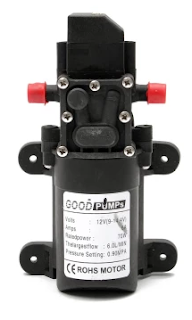
    3. Water Pump
         
         Water pump is a mechanical device that moves fluid or gas by pressure or suction.
         
         Specification of product :
  • Volts : 12V DC, 220 VAC
  • Amps : 6A
  • Rated Power : 70W
  • Pressure : 0.90 MPA (MAX 130 PSI)
  • Flow capacity : 6L / Min (6.0 Liters per minute)
  • Medium temperature : 0  ͒C - 100  ͒C
  • Inlet and Outlet size : 10mm
  • Weight : 598g (straight)
          Features :
  • Diaphragm pump combines the advantages of self-priming pump and chemical pump. Installed in a dry, well-ventilated location; pumps can not work in water.
  • Using a variety of imported corrosion-resistant materials, self-priming, thermal protection, smooth operation, long-time continuous idling, long-time continuous load operation.
  • Totally sealed, high stable pressure.
  • Rubber bracket can absorb vibration from the pump when working.
  • When the water pressure is too high, pump will protect themselves and normal work, water pipes will not burst, it is safe and durable.
  • Pressure protection : pressure switch power protection.
  • The maximum flow of 6 L /min, flow rate can be adjusted form 0.1 to 6 liters / min depending on the needs.
    Maximum pressure 130psi (9.0kg) of pressure can be adjusted from 75psi -130psi according to different needs.
  • The work : intermittent service (continuous working at different working pressure at different times).
  • The use of media : water or solvent pH value 5-8, oil.
  • Service life : more than 500-1000 hours of continuous work.
  • Pressure Switch Type Features : When the water turned off, it will automatically cut off power, the motor is stopped. After the water turned on, will automatically power on, motor running.


    4. 


LITERATURE REVIEW


Journal 2
This week I want to share a useful tips when selecting a sensor.

There are 6 thing that can be consider:

  1. Accuracy & Precision - Those two terms do not mean the same thing, though they are often related. Accuracy has to do with how close the sensor reading is to the true value while Precision refers to the ability of the sensor to detect small changes. (As an example, a temperature sensor that measures boiling water at 97.53  ͒C has a high precision but low accuracy.) Both the accuracy and precision of a given instrumentation system must be appropriate for the requirements of the system. Too high precision can give a false impression that the reading is also accurate or can result in the system detecting noise rather than the actual desired data. A sensor with more accuracy that necessary will be more expensive and more difficult to use properly than one more appropriate to the measurement required. Additionally, both accuracy and precision are affected by errors incurred throughout the system. Transducer error, wiring, signal conditioners, and the gauges or converters used to read the value each add their own errors into the system that must be understood in order to select the appropriate sensors.
  2. Environment - Selection of the proper sensor requires a good understanding of the environment in which the instrument will be operated. Many sensors can be affected by the non-ideal conditions of a production floor (such as temperature variation, vibration, humidity, chemicals, etc.) It is important to take the environment into account when selecting the sensor and its packaging, mounting, and other options.
  3. Excitation - Many transducers require power to produce an output signal and it is important to provide a power source that will not introduce additional errors.
  4. Signal Conditioning - Unfortunately, the world is full of non-ideal realities in sensors. Electrical noise is always present, often more so on production floors, and can cause erroneous readings. Signal conditioners and other protection circuits can provide some protection from these effects before conversion. Sometimes these are useful, but other times it is possible or preferred to process the signals after conversion, so the use of conditioners must be evaluated during the instrumentation design process.
  5. Conversion - In modern systems, it is often preferred that instrumentation system provide digital data (rather than analog gauges or chart recorders). The analog to digital converters must be evaluated and matched appropriately to the sensors or errors can be introduced, or money wasted by overpaying for precision in one that is not present in the other. Make sure to properly handle ratiometric and non-ratiometric sensors by properly matching with converters that are the same.
  6. Processing - Even if signal conditioning is performed, the sensor and conversion process is full of various sources of error. Some of these errors are linear (consistent effect across the measurement range), while others are non-linear. There are various methods and algorithms that can be used to compensate for these errors or to extract the best possible signal form the system.
The date ultimately must be displayed or used by the system and may be stored for later analysis. Whatever is done with the data, remember that a test system can only perform as well as the data it is provided, so appropriate analysis must be done when selecting and implementing the instrumentation.

Credit to : Ria Sood, Manjit Kaur and Hemant Lenka (June 2013) "Design and Development of Automatic Water Flow Meter."


VIDEO